Ship Form Coefficients
Ship form coefficient is used to describe hull shapes and compare different hulls. During design recommended values for each coefficient can be found in literature to give a starting point when designing the most optimum hull shape for the given application.
Symbols used in the following article
| Symbol | Description |
|---|---|
| L | Length |
| B | Beam |
| T | Draft or draught |
| Ax | Section area |
| Az | Water plane area |
| ∇ | Displacement (displaced volume) |
| zk | z-coordinate for the keel |
| zw | z-coordinate for the waterline |
| xa | The most aft part of the waterline |
| xf | The most forward part of the waterline |
| ⨂ | Midship location |
| Coordinate system | |
| x | Ship longitudinal direction |
| y | Transverse direction |
| z | Vertical direction with 0 typically being at the keel |
Waterplane Area Az
The waterplane area is determined by integrating y(x,z) from the aft part of the waterline xa to the forward part xf. The integral below is valid for symmetrical hulls with x being the axis of symmetry i.e. normal hull shapes.
Numerical integration can be done using this calculator or by using the trapezoidal rule or the Simpson's rule described in this article.
The geometric center of each waterplane is determined using the integral below. Similarly to above it is only valid for symmetrical hull shapes.

Section Area Ax
The section area Ax is the area of the transverse sections as illustrated by the example below. This can be at the same x-coordinates as the frames but not necessarily.

The section area at each x is for a symmetrical hull with x being the the axis of symmetry calculated as shown below.
The geometric center of each section is calculated using the equation below. \( \overline{y}(x,z_w) \) is zero as the hull is assumed symmetrical.
Below is an example of a cross-sectional area where the section area is calculated at difference stations (x-values) and at different drafts (zw).

∇ - Displacement
The displacement or volume of the underwater hull can either be determined by integrating the section areas (Ax(x,zw)) or by integrating the the water plane areas (Az(z))
LCB and VCB (KB) - Center of Buoyancy
The longitudinal center of buoyancy (LCB) and the vertical center of buoyancy (VCB or KB) can either be calculated using the sectional areas and the geometric center of each section or by using the water plane area and the geometric center of each water plane. The result will be the same if done correctly. The transverse center of buoyancy (TCB) is equal zero for typical symmetrical hull shapes but can otherwise be calculated using the same approach as the one used to calculate LCB and VCB.
LCB - Longitudinal Center of Buoyancy
VCB - The Vertical Center of Buoyancy
The vertical center of buoyancy is known as both VCB and KB with KB being named after keel to buoyancy.
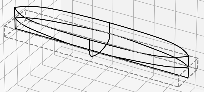
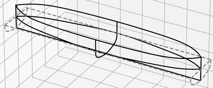
CB - Block Coefficient
The block coefficient is a dimensionless ratio between the displacement and the displacement of a rectangular with the size of LBT. It is a measure of the ships fullness e.g. a container vessel will have a block coefficient around 0.55 whereas a tanker will have a block coefficient at about 0.85.
CP - Prismatic Coefficient
The prismatic coefficient is the dimensionless ratio between the displacement and the volume of the prism with a transverse section equal to the midship section.
The prismatic coefficient can also be calculated from the block coefficient (CB) and the midship section coefficient (CM)
Cw - Water Plane Coefficient
The water plane coefficient is the ratio between the water plane area and the rectangle formed by LxB.

CM - Midship Section Coefficient
The midship section coefficient. \( A_x(\bigotimes ,z_w) \) is the section area of the midship section.

SR - Slenderness ratio
The slenderness ratio is a measure of the waterline length to the displacement.